前回 は、三角形の描画に必要なシェーダを実装しました。
今回は、そのシェーダを使って、実際に三角形を表示するためのWebGPUのコードを実装します。
シェーダをWebGPUに渡す
シェーダを動かすには、シェーダのコード(WGSLコード)をGPUが理解できる形式に変換してから、GPUに渡す必要があります。
WGSLコードをGPUが理解できる形式に変換する作業をコンパイルといいます。
WGSLコードのコンパイルは、WebGPU内部で行ってくれますが、そのためにはWGSLコードをWebGPUに登録する必要があります。
シェーダモジュールの作成
WGSLコードをJavaScriptからWebGPUに渡すときに使うのが、device.createShaderModule()メソッドです。
このメソッドにWGSLコードを文字列として渡すことで、シェーダモジュール(GPUShaderModule)というオブジェクトが作られます。
単なる文字列だったWGSLコードを、描画処理を構成する1つの部品(モジュール)としてWebGPUが使えるようにしたものが、シェーダモジュールです。
実際に、前回実装したWGSLコードを文字列として渡して、シェーダモジュールを作成するコードは次のようになります。
const shaderModule = device.createShaderModule({
  code: `
    struct VertexInput {
      @builtin(vertex_index) VertexIndex: u32
    };

    struct VertexOutput {
      @builtin(position) Position: vec4f
    };

    @vertex
    fn vs_main(in: VertexInput) -> VertexOutput {
      var pos = array<vec2f, 3>(
        vec2f( 0.0,  0.5),
        vec2f(-0.5, -0.5),
        vec2f( 0.5, -0.5)
      );

      var out: VertexOutput;
      out.Position = vec4f(pos[in.VertexIndex], 0.0, 1.0);
      return out;
    }

    @fragment
    fn fs_main() -> @location(0) vec4f {
      return vec4f(0.918, 0.561, 0.918, 1.0);
    }`
})
補足:Viteなどのビルドツールを使う
先ほど示したような、シェーダのコードをJavaScriptの文字列として埋め込む方法では、エディタのシンタックスハイライト機能の恩恵を受けられないですし、JavaScriptのコード全体が読みづらくなります。
シェーダのコードを別ファイルに分けて書きたい場合は、Viteなどのビルドツールを使うと便利です。
たとえば、Viteでビルドする場合は、shader.wgslという別ファイルに書いたシェーダのコードを、次のように.js(.ts)ファイルでimportして使うことができます。
// ?rawをつけることで、シェーダのコードを文字列としてimportできる
import shaderCode from "./shader.wgsl?raw"

const shaderModule = device.createShaderModule({
  code: shaderCode
})
シェーダの使い方を伝える仕組み
シェーダを意図通りGPUに使ってもらうためには、GPUに対してさまざまな補足説明を伝える必要があります。
レンダーパイプライン
WebGPUでは、レンダーパイプライン(GPURenderPipeline)というオブジェクトに、シェーダの実行に関する設定を詰め込みます。
- シェーダーの設定:どのシェーダーを使うか
- 入力レイアウト:頂点データの構成はどうなっているか
- レンダーターゲットの設定:色をどう合成するか(ブレンド)etc.
- プリミティブの設定:どのように頂点を結ぶか
- 深度ステンシルの設定
- マルチサンプリングの設定
言うなれば、レンダーパイプラインはシェーダの調理法を詰め込んだレシピです。
補足:パイプラインという名前の解釈
グラフィックスAPIにおいて、パイプラインは「処理の流れ」のような意味を持つ言葉です。
たとえば、GPUのパイプラインは「頂点シェーダ→ラスタライズ→フラグメントシェーダ」という流れで処理を行います。
WebGPUにおけるGPURenderPipelineオブジェクトは、パイプラインの各処理工程に対して、それぞれ「どんな設定に基づいて処理してほしいか」をまとめて定義したものといえます。
その処理工程ではどういう「状態」であってほしいか、WebGLではグローバルに散らばっていた状態を、WebGPUではレンダーパイプラインというオブジェクトに閉じ込めてしまうのです。設定をオブジェクト化することにより、その設定を使い回すことも容易になります。
レンダーパイプラインを作成する
レンダーパイプラインは、device.createRenderPipeline()メソッドで作成します。
このメソッドの引数には、さまざまな設定をオブジェクトに詰め込んで渡します。とはいえ、三角形を描くだけなら、あまり多くの設定は必要ありません。
const renderPipeline = device.createRenderPipeline({
  layout: "auto",
  vertex: {
    module: shaderModule,
    entryPoint: "vs_main"
  },
  fragment: {
    module: shaderModule,
    entryPoint: "fs_main",
    targets: [
      {
        format: canvasFormat
      }
    ]
  }
})このうち、layout: "auto"という部分は、今回の例ではあまり重要ではありません。次回の内容と密接に関わる部分なので、今の時点ではおまじないとしておきます。
それ以外の部分を詳しく見ていきましょう。
頂点シェーダの設定
描画にあたって「どのシェーダを使うのか?」という設定は、レンダーパイプラインで必須となります。
まず、使用する頂点シェーダの情報は、vertexプロパティに指定します。
必ず含めなければならないのは、次の2つの情報です。
vertex.module:頂点シェーダのコードを含むシェーダモジュールvertex.entryPoint:シェーダのコードのうち、どの関数を頂点シェーダとして実行するか
const renderPipeline = device.createRenderPipeline({
  layout: "auto",
  vertex: {
    module: shaderModule,
    entryPoint: "vs_main"
  },
  fragment: {
    // ...
  }
})vertex.moduleには、先ほど作成したシェーダモジュールを指定しています。
vertex.entryPointには、"vs_main"という文字列を指定しました。
これは、前回実装したシェーダのコードの中で、@vertexという印をつけて定義した関数の名前です。
@vertex
fn vs_main(in: VertexInput) -> VertexOutput {
  // ...
}
フラグメントシェーダの設定
使用するフラグメントシェーダの情報は、fragmentプロパティに指定します。
指定する内容は、頂点シェーダとほぼ同様です。
fragment.module:フラグメントシェーダのコードを含むシェーダモジュールfragment.entryPoint:シェーダのコードのうち、どの関数をフラグメントシェーダとして実行するか
const renderPipeline = device.createRenderPipeline({
  layout: "auto",
  vertex: {
    module: shaderModule,
    entryPoint: "vs_main"
  },
  fragment: {
    module: shaderModule,
    entryPoint: "fs_main",
    targets: [
      {
        format: canvasFormat
      }
    ]
  }
})
レンダーターゲットの設定
vertexと唯一異なる点として、fragmentにはtargetというプロパティも含まれています。
const renderPipeline = device.createRenderPipeline({
  layout: "auto",
  vertex: {
    module: shaderModule,
    entryPoint: "vs_main"
  },
  fragment: {
    module: shaderModule,
    entryPoint: "fs_main",
    targets: [
      {
        format: canvasFormat
      }
    ]
  }
})fragment.targetsには、フラグメントシェーダで計算した色をどこに出力するか?(レンダーターゲット)を指定します。
このtargetsが配列になっているのは、WebGPUでは、複数のレンダーターゲット(画像)に同時に出力することができるからです。
TIP
前回解説した、何番目のテクスチャに出力するのかというセクションを復習してみましょう。
今回は、キャンバスに描画するだけなので、targetsには1つだけ要素を指定します。
このとき、targets[0].formatには、getPreferredCanvasFormat()メソッドで取得した、キャンバスに最適なフォーマットを指定します。
つまり、context.configure()メソッドの引数に指定したformatと同じものです。
// ...

const canvas = document.querySelector("canvas")
const context = canvas.getContext("webgpu")

const canvasFormat = navigator.gpu.getPreferredCanvasFormat()
context.configure({ device, format: canvasFormat })

// ...

const renderPipeline = device.createRenderPipeline({
  // ...
  fragment: {
    module: shaderModule,
    entryPoint: "fs_main",
    targets: [
      {
        format: canvasFormat
      }
    ]
  }
})さらに注意が必要なのは、beginRenderPass()の引数となるrenderPassDescriptorのcolorAttachmentsでも、出力先に関する設定を行っていることです。
もしも出力先が複数ある場合は、renderPipelineのfragment.targetsと、renderPassDescriptorのcolorAttachmentsに、同じ順番で出力先を指定する必要があります。
今回は出力先は1つだけですが、targets[0]とcolorAttachments[0]がどちらも同じ出力先(キャンバス)を表していることを意識しておきましょう。
const renderPipeline = device.createRenderPipeline({
  // ...
  fragment: {
    module: shaderModule,
    entryPoint: "fs_main",
    targets: [
      {
        format: canvasFormat
      }
    ]
  }
})

// ...

const renderPassDescriptor = {
  colorAttachments: [
    {
      view: context.getCurrentTexture().createView(),
      loadOp: "clear",
      clearValue: { r: 0.749, g: 0.925, b: 1.0, a: 1 },
      storeOp: "store"
    }
  ]
}

// ...そして、targets[0]とcolorAttachments[0]に指定した出力先は、フラグメントシェーダの@location(0)指定つきの出力に対応しています。
@fragment
fn fs_main() -> @location(0) vec4f {
  // ...
}もしも出力先が複数ある場合は、さらにtargets[1]とcolorAttachments[1]に指定した出力先がフラグメントシェーダの@location(1)指定つきの出力に対応し、…というように、順番を揃えて出力先を指定する必要があるということです。
レンダーパイプラインを使う
レンダーパイプラインは、GPUの描画処理の根幹を担うシェーダに関する設定をまとめたものです。
このレンダーパイプライン(描画設定)で描画を行うには、renderPass.draw()メソッドを呼び出す前に、同じくrenderPassが持つsetPipeline()メソッドによって、レンダーパイプラインを使用するように指示します。
const renderPass = commandEncoder.beginRenderPass(renderPassDescriptor)
renderPass.setPipeline(renderPipeline)
renderPass.draw(3)
renderPass.end()
こうすることによって、GPUはレンダーパイプラインに込められた「どう描画すべきか?」のルールに従って、描画を実行してくれます。
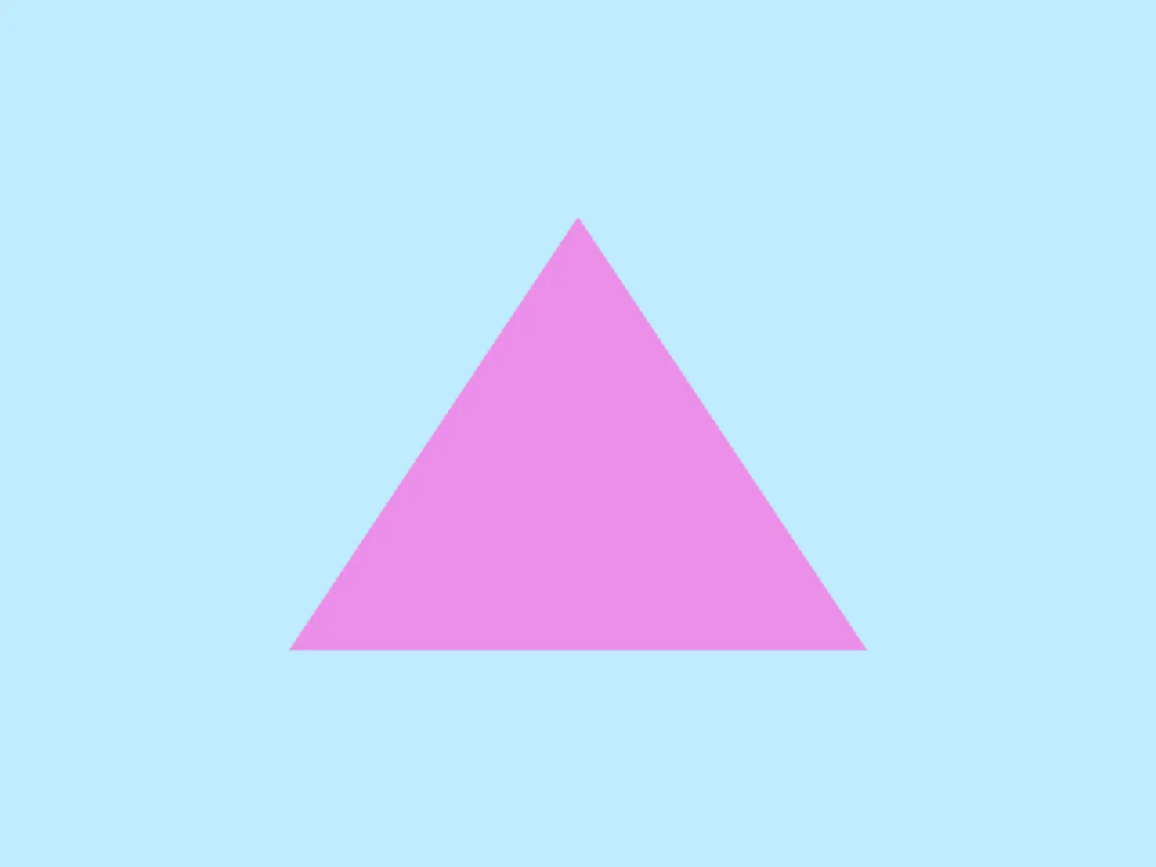
実装:キャンバスに三角形を描画する
これでようやく、キャンバスに三角形を描画するためのコードが出揃いました。
以下に、そのコードの全文を示します(※エラー処理は省略しています)。
struct VertexInput {
  @builtin(vertex_index) VertexIndex: u32
};

struct VertexOutput {
  @builtin(position) Position: vec4f
};

@vertex
fn vs_main(in: VertexInput) -> VertexOutput {
  var pos = array<vec2f, 3>(
    vec2f( 0.0,  0.5),
    vec2f(-0.5, -0.5),
    vec2f( 0.5, -0.5)
  );

  var out: VertexOutput;
  out.Position = vec4f(pos[in.VertexIndex], 0.0, 1.0);
  return out;
}

@fragment
fn fs_main() -> @location(0) vec4f {
  return vec4f(0.918, 0.561, 0.918, 1.0);
}const adapter = await navigator.gpu.requestAdapter()
const device = await adapter.requestDevice()
const canvas = document.querySelector("canvas")
const context = canvas.getContext("webgpu")
const canvasFormat = navigator.gpu.getPreferredCanvasFormat()
context.configure({ device, format: canvasFormat })
const shaderModule = device.createShaderModule({
  code: `(WGSL code)`
})
const renderPipeline = device.createRenderPipeline({
layout: "auto",
vertex: {
module: shaderModule,
entryPoint: "vs_main"
},
fragment: {
module: shaderModule,
entryPoint: "fs_main",
targets: [
{
format: canvasFormat
}
]
}
})
const commandEncoder = device.createCommandEncoder()
const renderPassDescriptor = {
colorAttachments: [
{
view: context.getCurrentTexture().createView(),
loadOp: "clear",
clearValue: { r: 0.749, g: 0.925, b: 1.0, a: 1 },
storeOp: "store"
}
]
}
const renderPass = commandEncoder.beginRenderPass(renderPassDescriptor)
renderPass.setPipeline(renderPipeline)
renderPass.draw(3)
renderPass.end()
device.queue.submit([encoder.finish()])device.createShaderModule()メソッドのcodeの値は、'(WGSL code)'という仮の文字列で省略表記しています。
この文字列を実際のWGSLシェーダのコードに置き換えてから、動作を確認してみてください。
const shaderModule = device.createShaderModule({
code: `(WGSL code)`
})実行結果は次のようになります。